
Driveshafts — Reassembly (cont'd)
10-5prose procedureDynamic damper band dimensions differ by market/engine: KQ/KY models; KG, KS and KW (SOHC) models; Other models.
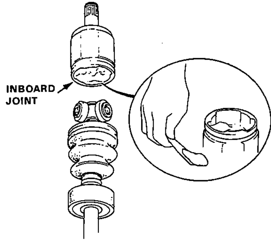
- 8Pack the inboard joint with molybdenum disulfide grease. Grease Quantity: 120–130 g
- 9Fit the inboard joint onto the driveshaft.CAUTION: Hold the driveshaft assembly so the inboard joint points up, to prevent it from falling off.
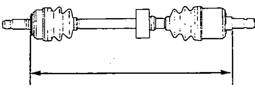
- 10Adjust the length of the driveshafts to the figure below, then adjust the boots to halfway between full compression and full extension.NOTE: The ends of boots seat in the groove of the driveshaft and joint.
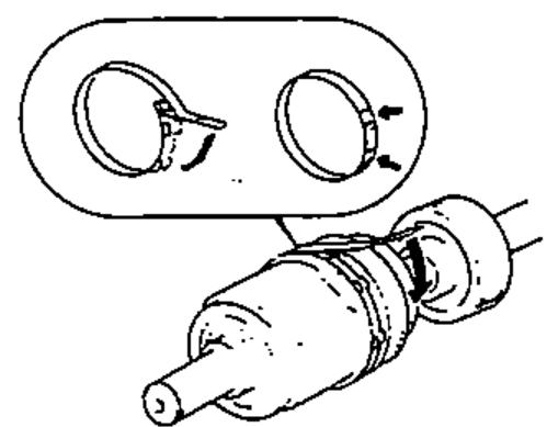
- 11Install new boot bands on the boot and bend both sets of locking tabs.
- 12Lightly tap on the doubled-over portions to reduce their height.
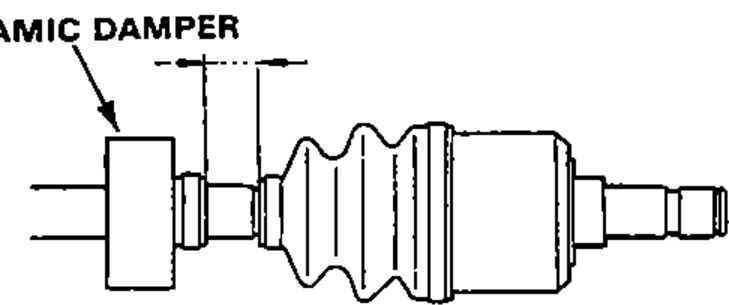
- 13Position the dynamic damper as shown below.
- 14Lightly tap on the doubled-over portion to reduce its height.
- 15Install a new dynamic damper band and bend down both sets of locking tabs.
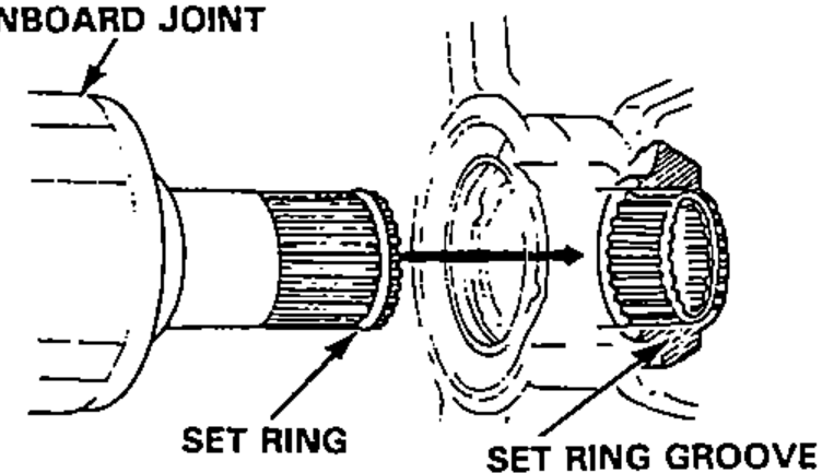
- 16Install a new set ring in the driveshaft groove.
- 17Install the inboard end of the driveshaft into the differential or intermediate shaft.Always use a new set ring whenever the driveshaft is being installed.Make sure the driveshaft locks in the differential side gear groove, and the CV joint subaxle bottoms in the differential or intermediate shaft.
- 18Refill the transmission.
With Intermediate Shaft
Left485–490 mm (19.09–19.29 in)
Right485–490 mm (19.09–19.29 in)
Without Intermediate Shaft
Left774.5–779.5 mm (30.50–30.69 in)
Right481.5–486.5 mm (18.96–19.15 in)
KQ, KY Models
Left30±2 mm (1.20±0.08 in)
Right30±2 mm (1.20±0.08 in)
KG, KS and KW (SOHC) Models
Left53.7±2 mm (2.10±0.08 in)
Right20±2 mm (0.78±0.08 in)
Other Models
Left25±2 mm (0.98±0.08 in)
Right30±2 mm (1.20±0.08 in)