Driveshafts — Removal
10-2prose procedureRemoval
- 1Loosen the front wheel lug nuts.
- 2Raise the front end of the car and place safety stands in the proper locations. Remove the front wheels.
- 3Drain the transmission oil.It is not necessary to drain the transmission oil when only the left driveshaft is removed.
- 4Raise the locking tab on the spindle nut and remove it with a 36 mm (1-7/16 in.) socket wrench.
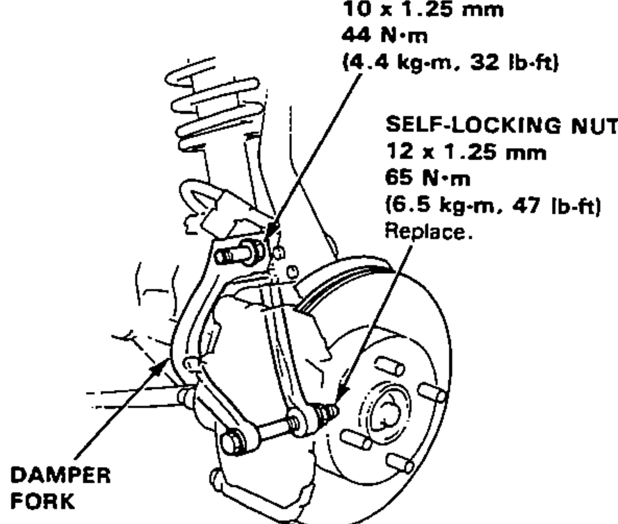
- 5Remove the damper fork nut and damper pinch bolt. Remove the damper fork.Damper pinch bolt (10 x 1.25 mm): 44 N·m (4.4 kg-m, 32 lb-ft)Self-locking nut (12 x 1.25 mm): 65 N·m (6.5 kg-m, 47 lb-ft) — Replace.
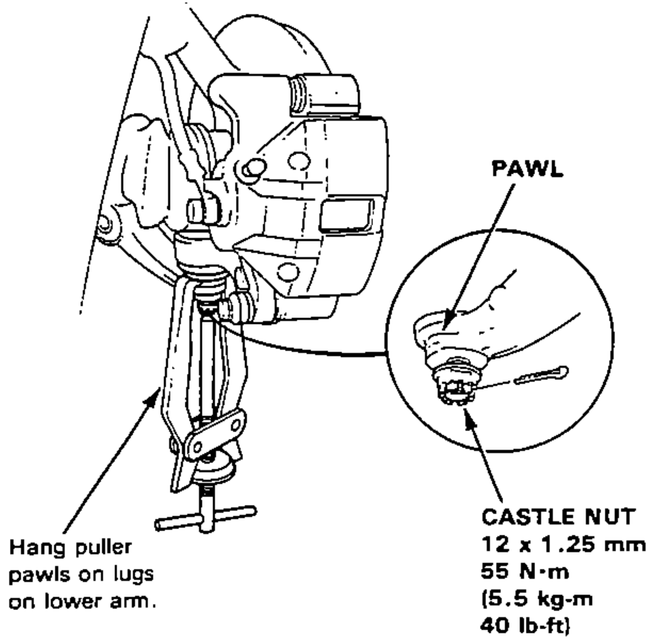
- 6Remove the knuckle-to-lower arm castle nut, and separate the lower arm from the knuckle using a puller with the pawls applied to the lower arm.Castle nut (12 x 1.25 mm): 55 N·m (5.5 kg-m, 40 lb-ft)
- 7Pull the knuckle outward and remove the driveshaft outboard joint from the knuckle using a plastic hammer.
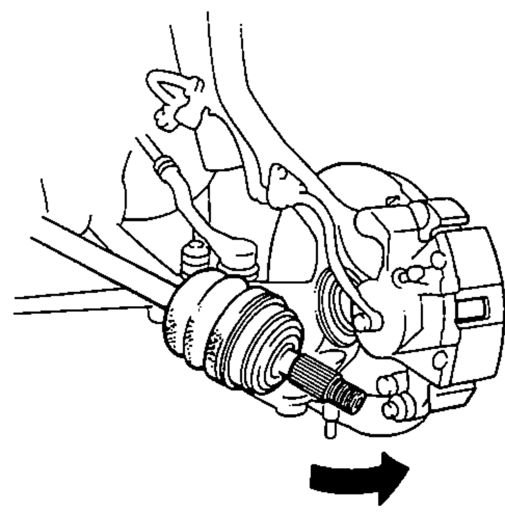
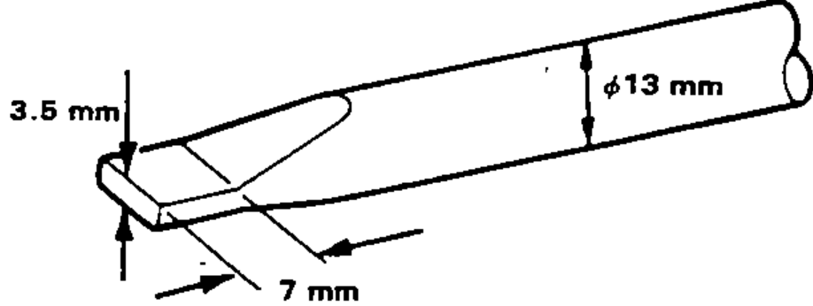
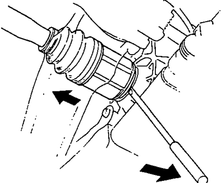
- 8Pry the driveshaft assembly with a screwdriver as shown to force the set ring at the driveshaft end past the groove.
- 9Pull the inboard joint and remove the driveshaft and CV joint out of the differential case as an assembly.Do not pull on the driveshaft, as the CV joint may come apart.Use care when prying out the assembly and pull it straight to avoid damaging the differential oil seal or intermediate shaft dust seal.
CAUTION
Do not pull on the driveshaft, as the CV joint may come apart. Use care when prying out the assembly and pull it straight to avoid damaging the differential oil seal or intermediate shaft dust seal.
| Specification | Value |
|---|---|
| Damper pinch bolt (10 x 1.25 mm) | 44N·m |
| Self-locking nut (12 x 1.25 mm) | 65N·m |
| Castle nut (12 x 1.25 mm) | 55N·m |
| Spindle nut socket size | 36 mm (1-7/16 in.) |
Damper pinch bolt (10 x 1.25 mm)
44N·m
Self-locking nut (12 x 1.25 mm)
65N·m
Castle nut (12 x 1.25 mm)
55N·m
Spindle nut socket size
36 mm (1-7/16 in.)