Preparation of Work (cont'd) - Electrical
1-11prose procedureElectrical-section steps are numbered 13-19 here for unique step IDs; on the page they are unnumbered bullets under the 'Electrical' heading.
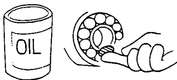
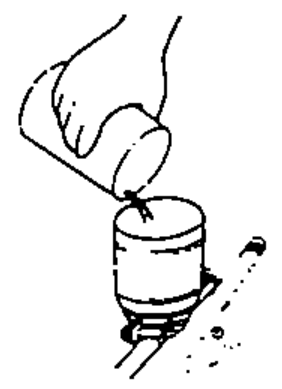
- 9Coat or fill parts with specified grease as specified (Page 4-2). Clean all removed parts with solvent upon disassembly.
- 10Brake fluid and hydraulic components
- 11Avoid oil or grease getting on rubber parts and tubes, unless, specified.
- 12Upon assembling, check every part for proper installation and operation.
Electrical
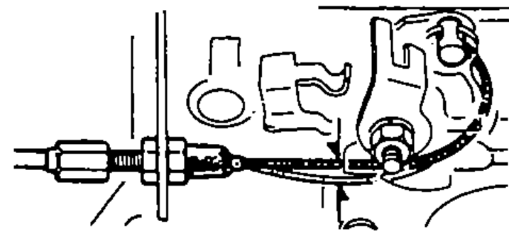
- 13Before making any repairs on electric wires or parts, disconnect the battery cables from the battery starting with the negative (-) terminal.
- 14After making repairs, check each wire or part for proper routing and installation. Also check to see that they are connected properly.
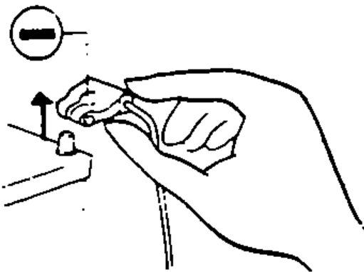
- 15Always connect the battery positive (+) cable first, then connect the negative (-) cable.
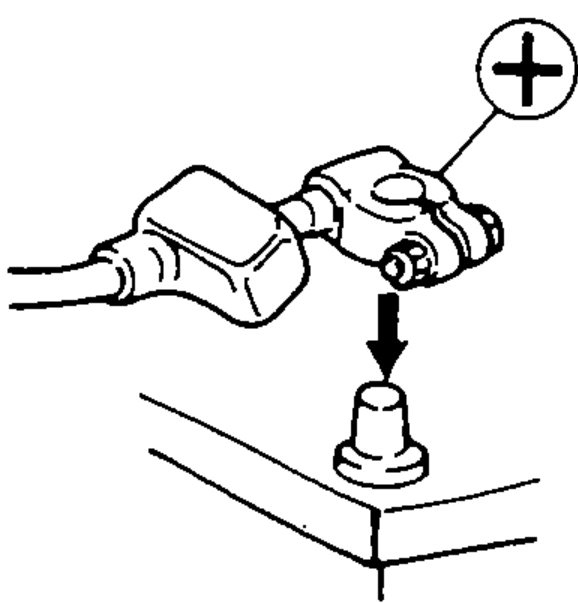
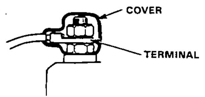
- 16Coat the terminals with clean grease after connecting the battery cables.
- 17Don't forget to install the terminal cover over the positive battery terminal after connecting.
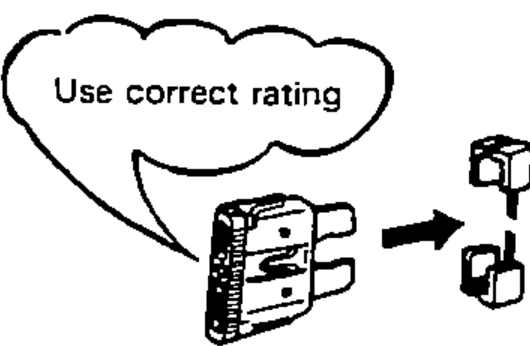
- 18Before installing a new fuse, isolate the cause and take corrective measures, particularly when frequent fuse failure occurs.
- 19Be sure to install the terminal cover over the connections after a wire or wire harness has been connected.