
Test
15-23prose procedureFan Switch
- 1Disconnect the 6P connector from the fan switch.
- 2Check for continuity between the terminals of the fan switch according to the table below.
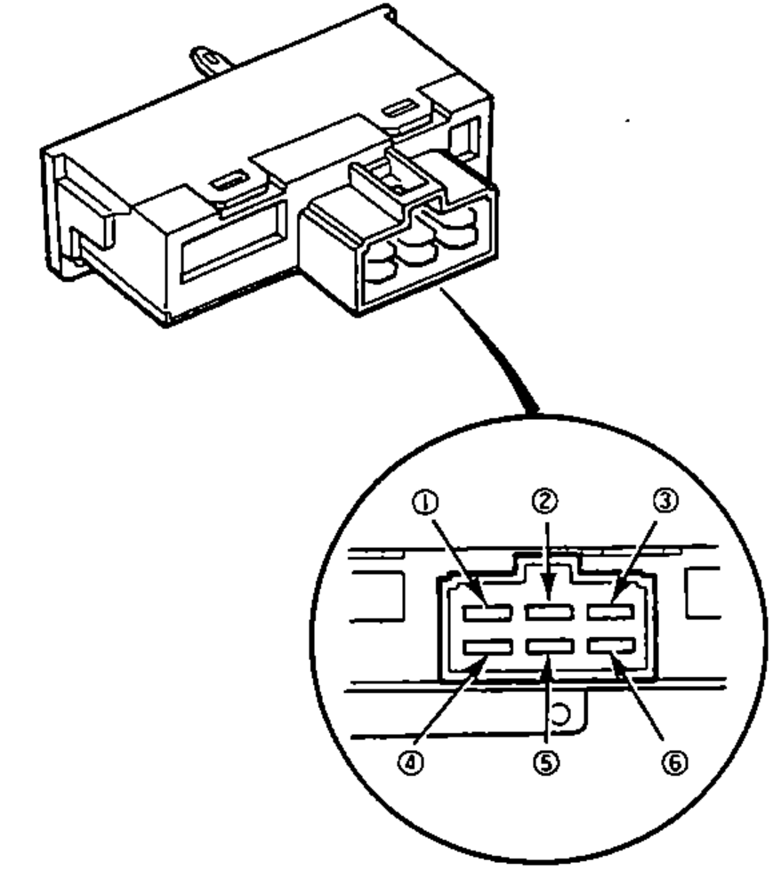
SWITCH CONNECTION
OFF
1
2
3
4
5
6
1
1O
2
3
4O
5
6O
2
1O
2O
3
4
5
6O
3
1O
2
3
4
5O
6O
4
1O
2
3O
4
5
6O
NOTE
In the SWITCH CONNECTION table, 'O' marks terminals connected (continuity) at each fan-switch position; connected terminals within a row are linked by a continuity line.
Recirculation Control Motor
- 1Connect the battery positive to the (3) terminal of the recirculation control motor connector and negative to (2) terminal.
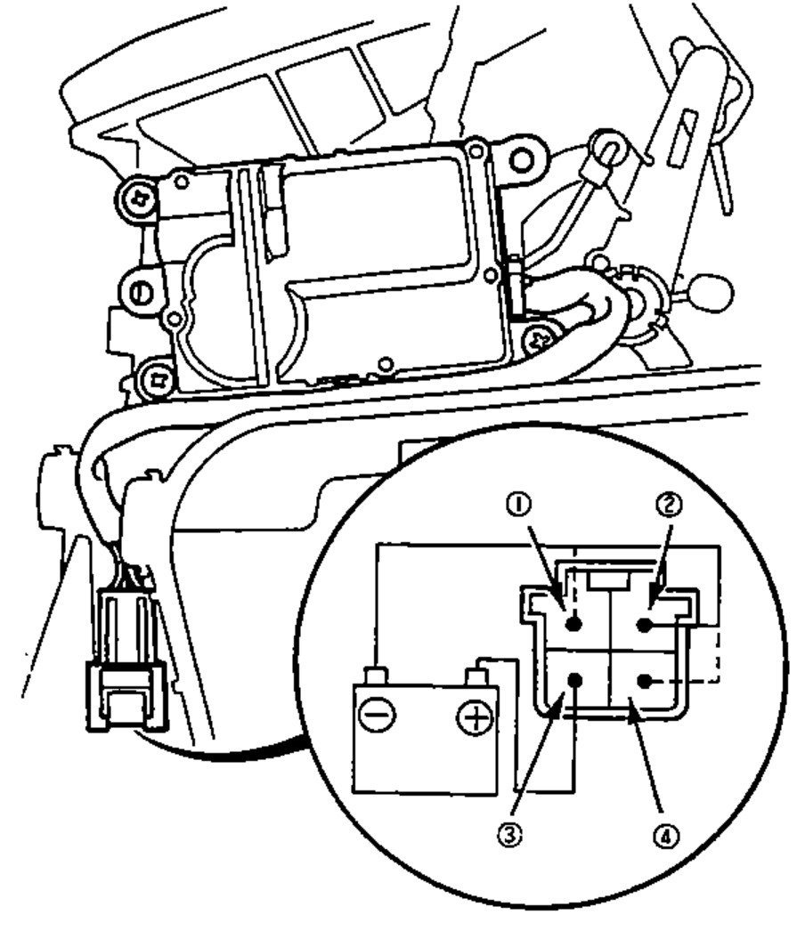
- 2Using a jumper wire connect the (2) terminal and (1) or (4) terminal.
- 4The motor automatically stops after half turn with the jumper wire connected.