
Test
15-24prose procedureFunction Control Switch
- 1Disconnect the 13P connector from the heater control.
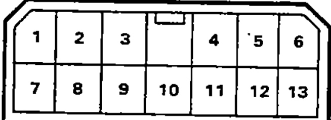
- 2Check for continuity between the terminals according to the table.
Vent (face) mode icon
4
10
9
3
8O
12 or 13O
Bi-level mode icon
4
10
9
3O
8
12 or 13O
Heat (foot) mode icon
4
10
9O
3
8
12 or 13O
Heat/defrost mode icon
4
10O
9
3
8
12 or 13O
Defrost (windshield) mode icon
4O
10
9
3
8
12 or 13O
NOTE
In the table, 'O' marks the terminals with continuity at each function-control position; each position connects one terminal to terminal 12 or 13. The Position column uses HVAC mode icons (approximate names given).
Function Control Motor
- 1Connect the battery positive terminal to the 5 terminal of the function control motor and negative to the 1 terminal.
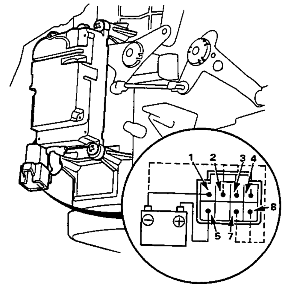
- 2Using jumper wire short the 1 terminal individually to the 2, 3, 4, 7 and 8 terminals to follow the order.