
Tilt Steering Column Reassembly (cont'd)
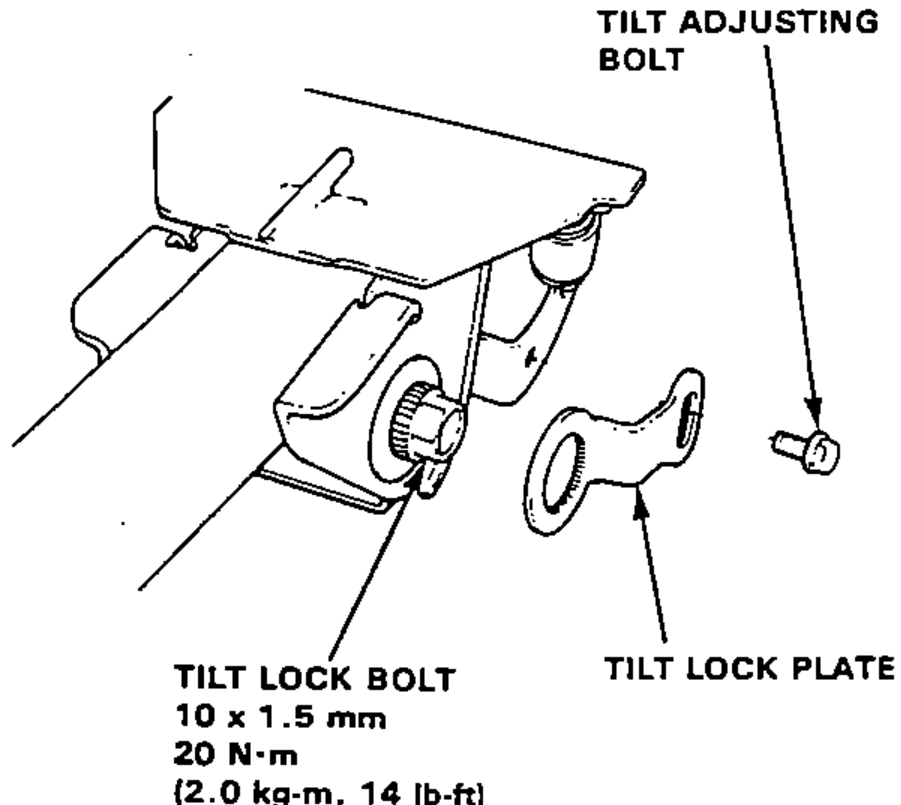
11-15prose procedure- 8Tighten the tilt lock bolt to 20 N·m (2.0 kg-m, 14 lb-ft), then position the tilt lock plate on the splined portion of the tilt lock bolt and loosely attach with the tilt adjusting bolt.
- 9Attach a spring scale 10mm (3.937in) from the end of the knob. Measure the force required to move the lever.
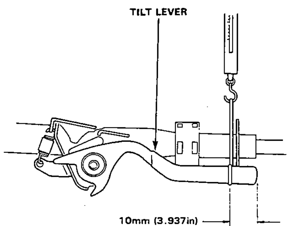
- 10If the force measured is not within the specification, remove the tilt lock plate then reset it in the position where the correct force can be obtained.
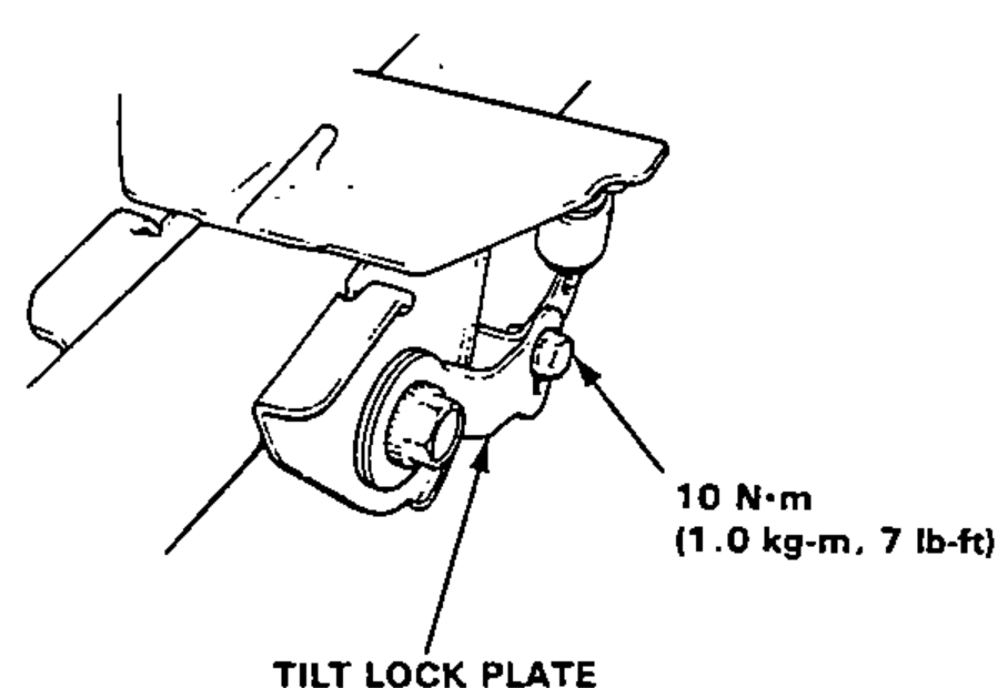
- 11Tighten the tilt adjusting bolt.
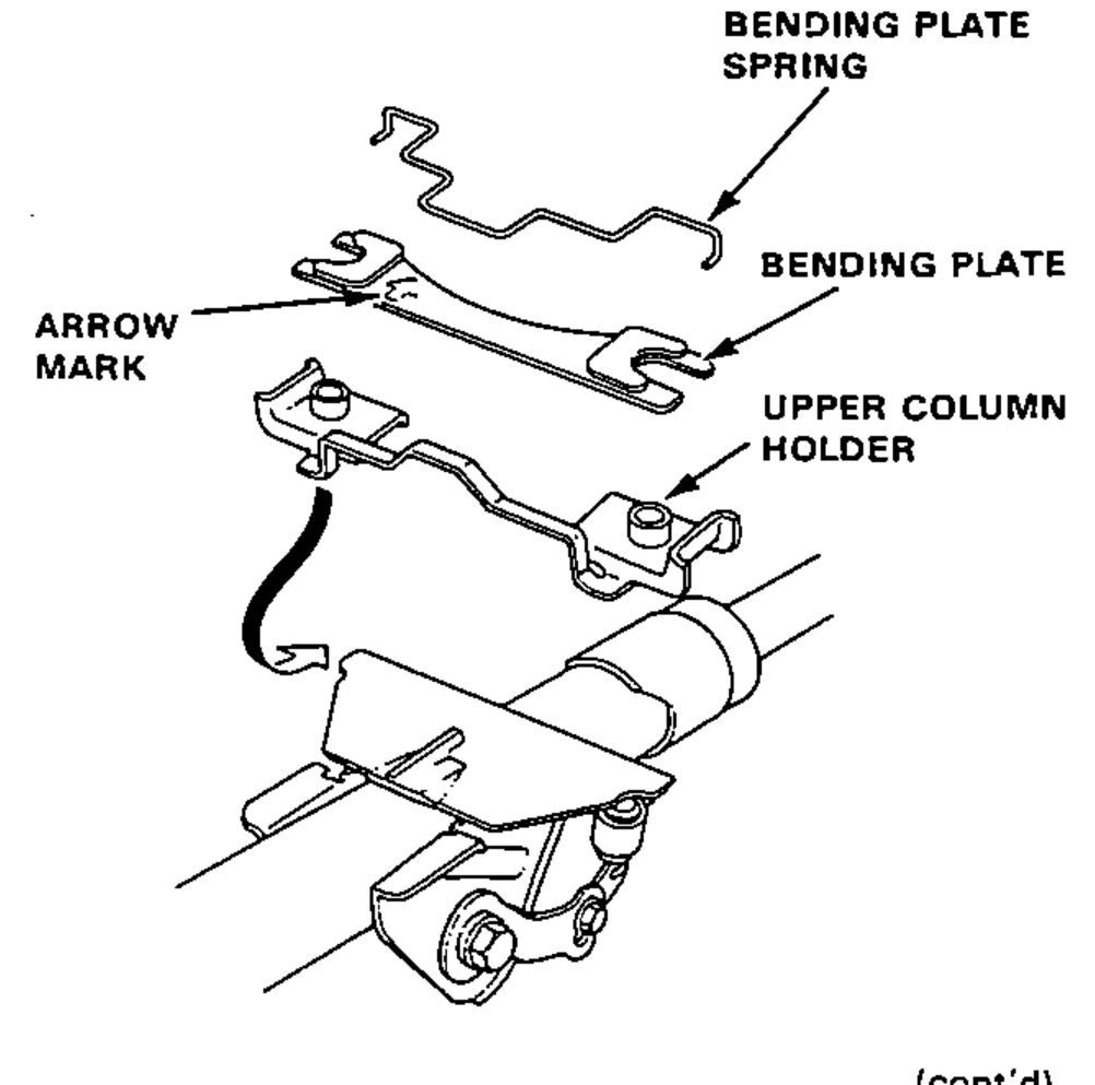
- 12Install the upper column holder and bending plate with the bending plate spring on the bending plate base.Install the bending plate with arrow mark facing the steering gearbox.
| Specification | Value |
|---|---|
| Tilt lock bolt | 20N·m |
| Tilt lock bolt size | 10 x 1.5 mm |
| Tilt lock plate force | 10N·m |
| Lever preload | 80N (8.0kg, 18lbs) |
Tilt lock bolt
20N·m
Tilt lock bolt size
10 x 1.5 mm
Tilt lock plate force
10N·m
Lever preload
80N (8.0kg, 18lbs)