Rear Window Defogger - Switch Removal / Switch Test
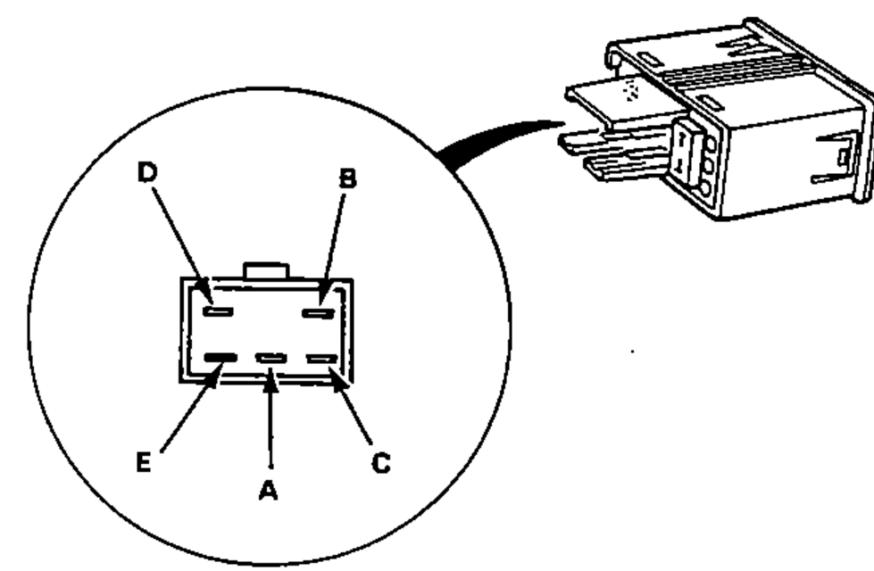
16-132prose procedureContinuity table transcribed from the switch-test grid; the ON-row jumper/bulb symbols across terminals A–E make the exact per-pin pairing hard to read, so the continuity groupings are approximate — verify against the internal schematic (fig4).
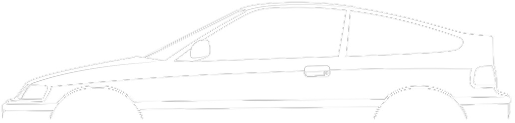
Switch Removal
- 1Pull out the switch from the instrument panel, then disconnect the 6-P connector from the switch.
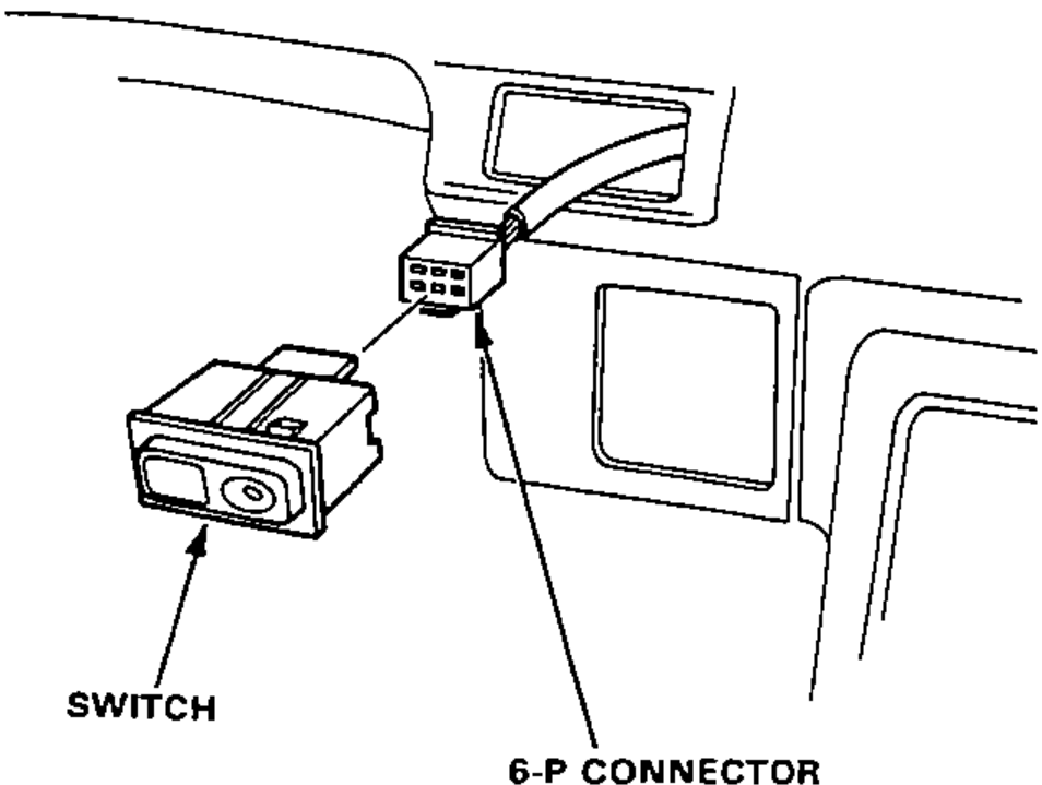
- 2Turn the socket 45° counterclockwise (1.4W) and pull out the socket (0.84W) to remove it.
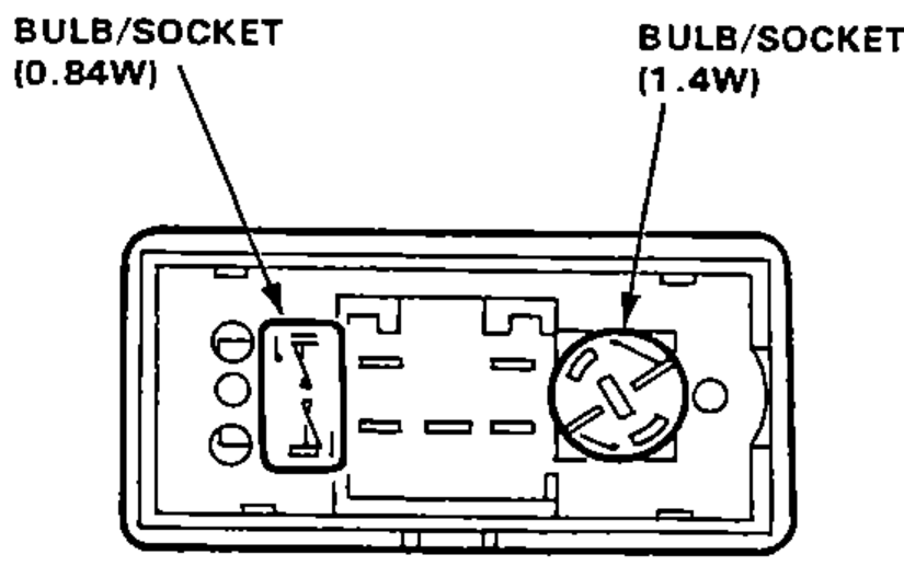
Switch Test
- 1Remove the switch from the instrument panel.
- 2Check for continuity between the terminals according to the table.
ON
Continuity between terminals A B C D EA–B continuity; C–D continuity (through indicator light); D–E continuity (through light)
OFF
Continuity between terminals A B C D ENo continuity