Ignition Switch
16-30prose procedureTest
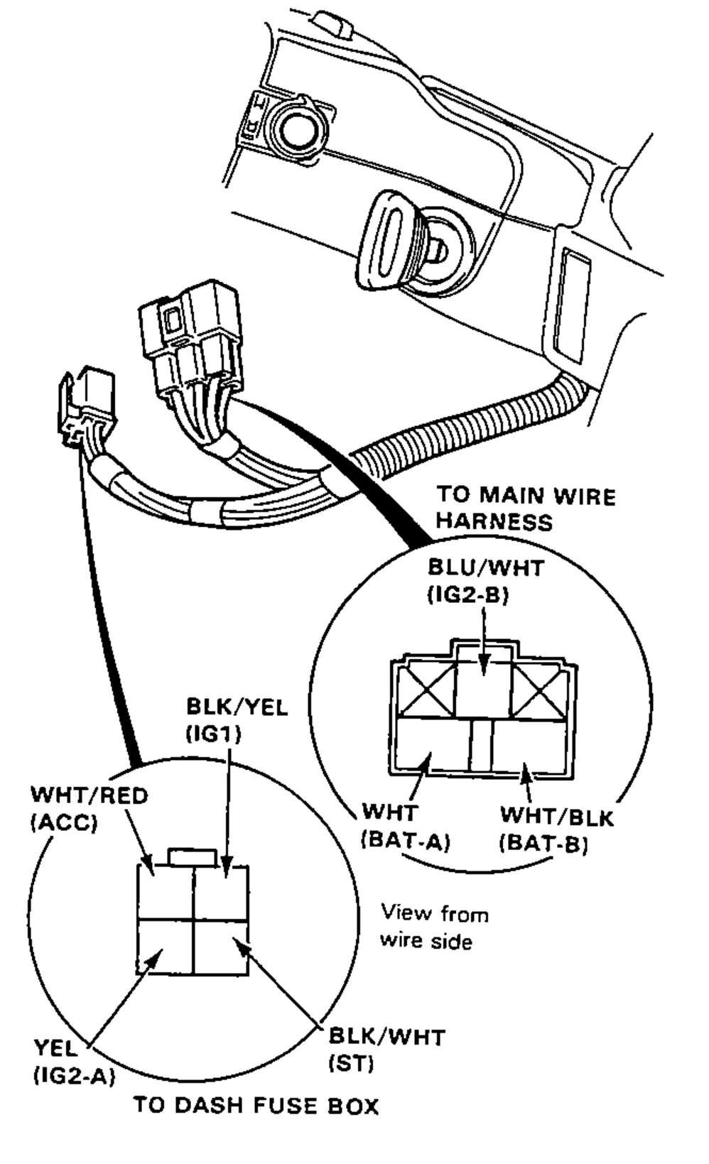
- 1Remove the dashboard lower panel.
- 2Disconnect the 4-P connector from the dash fuse box and 5-P connector from the main wire harness.
- 3Check for continuity between the terminals in each switch position according to the table.
0
WHT/RED (ACC)
WHT/BLK (BAT-B)
BLU/WHT (IG2-B)
WHT (BAT-A)
BLK/YEL (IG1)
YEL (IG2-A)
BLK/WHT (ST)
I
WHT/RED (ACC)O
WHT/BLK (BAT-B)O
BLU/WHT (IG2-B)
WHT (BAT-A)
BLK/YEL (IG1)
YEL (IG2-A)
BLK/WHT (ST)
II
WHT/RED (ACC)O
WHT/BLK (BAT-B)O
BLU/WHT (IG2-B)O
WHT (BAT-A)O
BLK/YEL (IG1)O
YEL (IG2-A)O
BLK/WHT (ST)
III
WHT/RED (ACC)
WHT/BLK (BAT-B)
BLU/WHT (IG2-B)
WHT (BAT-A)O
BLK/YEL (IG1)O
YEL (IG2-A)
BLK/WHT (ST)O
NOTE
Continuity table: 'O' marks terminals joined by a continuity line in that switch position. Position I: ACC-BAT-B. Position II: ACC-BAT-B-IG2-B joined, and BAT-A-IG1-IG2-A joined. Position III: BAT-A-IG1-ST joined.
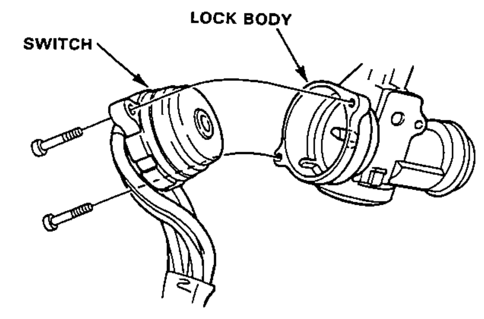
Electrical Switch Replacement
- 1Remove the dashboard lower panel.
- 2Remove the steering column lower cover.
- 3Disconnect the 4-P connector from the dash fuse box and 5-P connector from the main wire harness.
- 4Insert the key and turn it to "0."
- 5Remove the 2 screws and replace the base of the switch.