Brake Warning System
16-92prose procedureCircuit Check function of the brake warning system applies to the KQ model only. No.2 (10A) and No.1 (10A) fuses referenced in the dash fuse box.
Description
NOTE
Refer to page 16-81 for wiring description of the circuit check system.
Description: The brake warning light goes on if the parking brake is applied, if the brake fluid level is low, and as a circuit test while cranking the engine.
Parking Brake: With the ignition switch in "Run" or "Start", and the parking brake switch closed, the brake warning light operates to remind the driver that the parking brake is applied.
Brake Fluid Level: With the ignition switch in "Run" or "Start", and the brake fluid level switch closed, the brake warning light operates to warn the driver of low brake fluid level in the brake master cylinder.
NOTE
Low fluid level indicates brake wear or system leaks; check brake pad wear before adding fluid.
Circuit Check: KQ model only. With the ignition switch in "Start" voltage is applied through the No.2 (10A) fuse in the dash fuse box to the circuit check built into the integrated control unit. The circuit check transistor is on, and current flows through the No.1 (10A) fuse in the dash fuse box, the brake warning light and the circuit transistor to ground. The brake warning light operates. This operation tests the brake warning circuit and the circuit transistor to ground. The brake warning light operates. This operation tests the brake warning circuit and bulb.
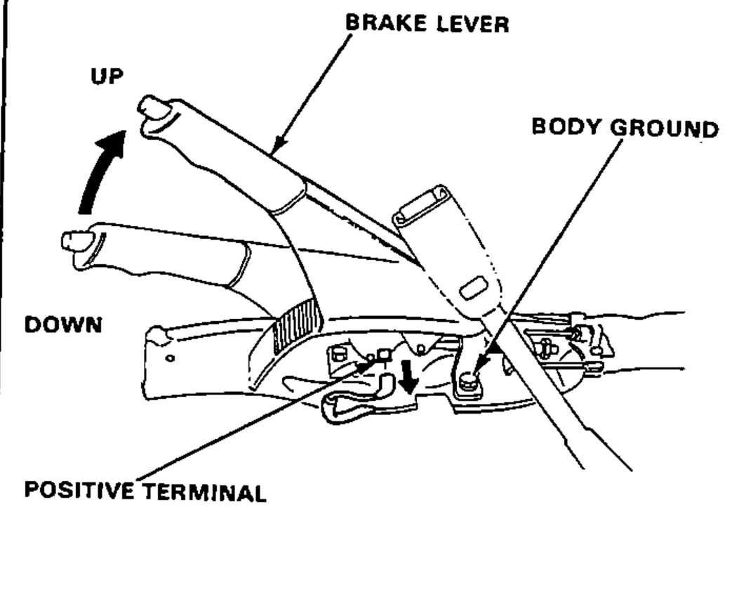
Parking Brake Switch Test
- 1Remove the center console and disconnect the connector from the switch.
- 2There should be continuity between the positive terminal and body ground with the brake lever up. There should be no continuity with the brake lever down.
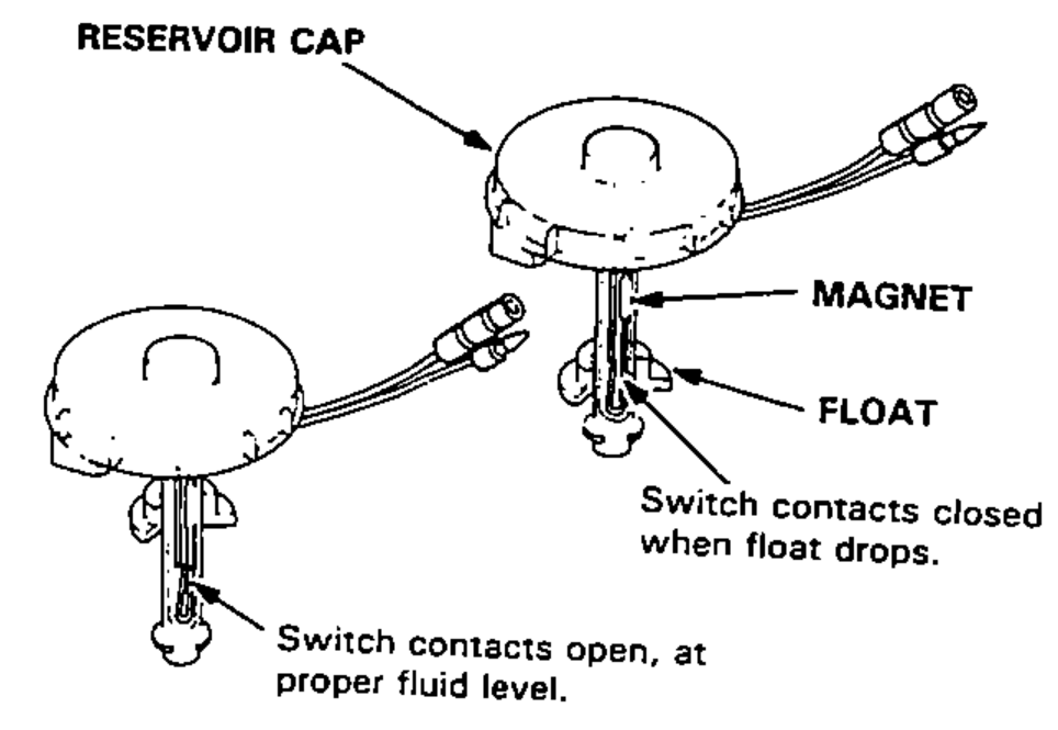
Brake Fluid Level Switch Test
- 1Remove the reservoir cap. Check that the float moves up and down freely. Replace the reservoir cap assembly if the float does not move freely.
- 2Check for continuity between the terminals with the float up and down. There should be continuity with the float down and no continuity with the float up. Replace the reservoir cap assembly if necessary.